Stable voltage or current sources are key requirements for most electronic applications and while there are many integrated solutions which provide these functions, they can be expensive and also consume power and valuable board space. Thankfully, these can still be implemented quickly and inexpensively using discrete devices and in this blog article, Nexperia shows how various voltage regulators and current stabilizers can be implemented using devices from its broad portfolio of discrete bipolar junction transistors (BJTs).
Voltage Regulation
Nowadays, switching regulators are widely used as power supplies but linear regulation is also required for applications where electromagnetic interference (EMI) and voltage ripple can be problematic, including application-specific chips (ASICs), microcontrollers, application processors and sensors. This is why linear regulators are now also included after switching regulators in almost every power supply block. Unlike in switching regulators, the difference between input and output power is dissipated in a pass device like a BJT (Figure 1). To minimize these power losses, linear regulators are mainly used in applications where the difference between input and output voltage is small, or where only small output currents are required. Figure 1 shows a basic linear regulator which employs feedback regulation and where the NPN pass transistor is driven by a PNP BJT.

The minimum voltage drop across the BJT output stage (Figure 1) is the sum of the emitter-collector saturation voltage of the PNP transistor and the voltage drop of the base emitter junction of the NPN:
VOUT(min) = VCEsat + VBE
The output voltage is regulated by an error amplifier which tracks it using a resistor divider. This feedback voltage is compared to a reference voltage (VREF) and the base drive of PNP-BJT is adjusted accordingly, which in turn adjusts the drive of the pass transistor. In this way, if the feedback voltage is above the reference voltage, the error amplifier lowers the base current, and vice versa.
Where lower accuracy voltage regulation and larger output currents (in the double-digit mA range) are required, a Zener diode, with VZ larger or equal to the desired output voltage and the maximum base emitter voltage can be used (Figure 2).

A more precise low dropout (LDO) regulator uses a shunt regulator like the TL431 or TLVH431 to drive the pass BJT (Figure 3). With this approach, the minimum output voltage is then given by:
VOUT(min) = Vref

Nexperia has a large portfolio of low-VCEsat BJTs which are ideal for use as pass devices in linear regulation applications. A comparison of features in some of these devices is shown in Table 1.

Products with “PA” in their name are available in a modern 2 mm × 2 mm leadless package, while products with “X” in their name come in a legacy SOT89 package (4.6 mm × 4.25 mm). The thermal performance of these devices for different load currents is shown in Figure 4.

Current Stabilization
Some loads, like an LED string, can’t be directly connected to a constant voltage source but still require a stable current. This scenario arises because the forward voltage of an LED is temperature dependent with a negative thermal coefficient, meaning current would continuously increase due to self-heating and/or increasing ambient temperature. This could eventually lead to thermal runaway, potentially destroying the LEDs in the string. Figure 5 shows how to implement a simple current sink using an NPN or a current source using a PNP BJT:
.2024-06-27-17-41-35.png)
.2024-06-27-17-41-35.png)
Figure 5 Basic BJT-based current sink and source
Here, the output current is given by:
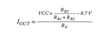
However, these basic circuits have the disadvantage that the stability of the output current is impacted by the negative temperature coefficient of VBE, which is approximately −2 mV/K, meaning the change in output current over temperature is:
ΔIOUT/ΔT = −2 mV/RE
This can be partially compensated by including a P-N or a Zener diode in the base bias circuit as shown in Figure 6. The benefit of using a Zener diode is that IOUT becomes independent of VCC, increasing its immunity to supply voltage ripple.

Very precise current stabilization can be achieved by combining a BJT with a base drive controller to provide an accurate and thermally compensated control loop. A shunt regulator, like the TL431 or TLVH431 can be used to implement such a solution (Figure 7).

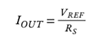
The shunt regulator controls the base voltage of the BJT so that the voltage drop at the sense resistor RS is the same as the reference voltage (VREF) of the controller IC so that the output current is then given by:
Summary
Voltage regulators and current stabilizers can be quickly and inexpensively implemented using devices from Nexperia’s broad portfolio of discrete BJTs.
To learn more about these and other BJT applications, download Nexperia’s Bipolar Junction Transistor Application Handbook at: