The USB Type-C® connector is a powerhouse - delivering up to 2 * 80 Gbps of data and 240 W of power through a single port. But with up to 48 V VBUS running close to sensitive SuperSpeed data lines, designers can face a critical challenge: how to protect these lines from Electro-Static Discharge (ESD) and short-circuit events. Due to their proximity to the neighboring VBUS lines, the AC coupled Tx/Rx lines need a special focus if short circuit events are to be expected in the application.
The USB Power Delivery specification [1] offers several safety features to avoid potential issues which might arise from this proximity. A common discussion point with interface designers is the availability of non-compliant cables, connectors or applications in the market, though.
The Design Dilemma
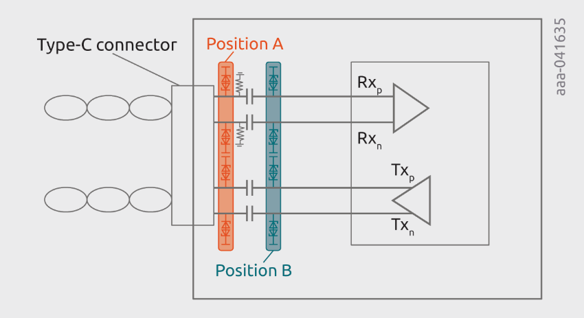
SuperSpeed lines are AC-coupled, offering two potential positions for ESD protection:
- Position A: Between the connector and the AC coupling capacitor
- Position B: Between the capacitor and the protected IC
Traditionally, Position A is favored to maximize trace length between ESD protection and protected IC, thus protection level. But what happens if stress conditions, like a VBUS short, come into play?

What the Data Shows
Nexperia’s latest investigation reveals a surprising truth:
- Low-voltage ESD diodes at Position B significantly reduce stress on the IC during both ESD and surge events; the latter is caused if VBUS is shorted to the AC coupling capacitance.
- High-voltage diodes at Position A may not activate early enough, allowing damaging current to reach the IC.
Even though Position B leaves the AC coupling capacitors exposed to ESD strikes, the TLP robustness levels of the capacitances investigated by Nexperia exceeded IEC61000-4-2 level 4 contact discharge.
Key Takeaway
Placing low-voltage ESD protection at Position B offers superior protection, even if it contradicts textbook layout advice. In a world of non-compliant cables and rising VBUS voltages, this insight could be the difference between a robust design and a costly failure.
Want the full technical breakdown, test data, and design recommendations?
Read the full whitepaper to explore Nexperia’s findings in detail.