USB Type-C bring many opportunities but also many challenges. One of these is how to avoid EMI issues with data-lines in the Gigahertz-range.
The new USB Type-C connector brings new opportunities, but also new challenges.
Let’s take a closer look at common mode filters (CMFs) to avoid EMI issues with data-lines in the Gigahertz-range, including:
- How to introduce a CMF for USB3.1 and HDMI2.0 without the need for a time-consuming re-design, if protection-and-filtering or protection-only need to be exchanged
- How to choose a CMF while still making sure, that a very-fast signal, such as USB3.1 and HDMI2.0, goes through.
- How additional ESD protection degrades the signal integrity of stand-alone CMFs.
- How CMFs are chosen to suppress common mode noise for the most critical frequencies.
- How to protect very sensitive transceivers for very fast data lines efficiently against ESD.
To copy content, like larger videos, on mobile applications, consumers expect higher data rates from their USB connector. In consequence, the industry is adapting USB3.1, which is also supported by the new USB Type-C connector.
However, by moving a data line with a fundamental of 2.5 or 5 GHz in an environment using wireless transmission in the same frequency range such as WiFi, Bluetooth and LTE, interference between these bands occurs, as reported in this whitepaper by Intel.
So, the USB Type-C connector opens new opportunities when it comes to the connectivity of portable devices. At the same time, the number of options increases the complexity of the application of this interface. New solutions are needed to reduce this complexity to support a faster time to market.
Taking a closer look at USB3.1, for example, the USB Type-C connector offers a very attractive way to integrate SuperSpeed USB into portable applications such as smart phones or tablets. It also offers the option to transmit high-speed Audio/Video data over the same interface.
By doing this, additional sources of noise are integrated into a compact application, which have their fundamental waves notably at 2.5 and 5 GHz for SuperSpeed USB. CMFs are a standard way of suppressing unwanted common mode noise to avoid interference between these fundamentals and wireless data bands at the same frequencies, such as WiFi, LTE and Bluetooth, while letting the differential signal pass.
Now, every designer would like to keep the Bill of Material small. So, there is the obvious question, whether a CMF is required in a specific design. Ideally, a combination with CMF can be compared to a combination without one, since EMI issues are difficult to predict in the design phase. Unless standard ESD protection, which does not interrupt the signal path, when not assembled, the footprint of a CMF will interrupt the signal lines. If the filter is not required, a “plug” with excellent RF data capabilities needs to bridge this gap. Alternatively, the board needs a new design cycle to close this gap.
Nexperia is one of the major suppliers of ESD protection for USB3.x since 2009. In our experience, transceivers for USB3 are very sensitive to ESD pulses and need very low-clamping ESD-protection. For this reason, it was almost natural to integrate the latest generation of very low-clamping ESD protection, TrEOS protection into this “plug,” which can replace the CMF. Naturally, TrEOS protection is used in the integrated CMF as well. By having the choice of CMF with ESD-protection and ESD-protection-only in the same footprint, the first board design will be the final design — at least for the protection and filtering part. It is even possible to offer CMF to some markets and go without CMF for other markets, in the same platform, without a time-consuming re-design. The CMF option can even be added after the market launch.
When choosing a CMF for USB3.1, the choice is PCMFxUSB3S (protection and common mode filtering, the “x” stands for the number of differential line-pairs), while the ESD-protection-only in the same footprint is named PESDxUSB3S.
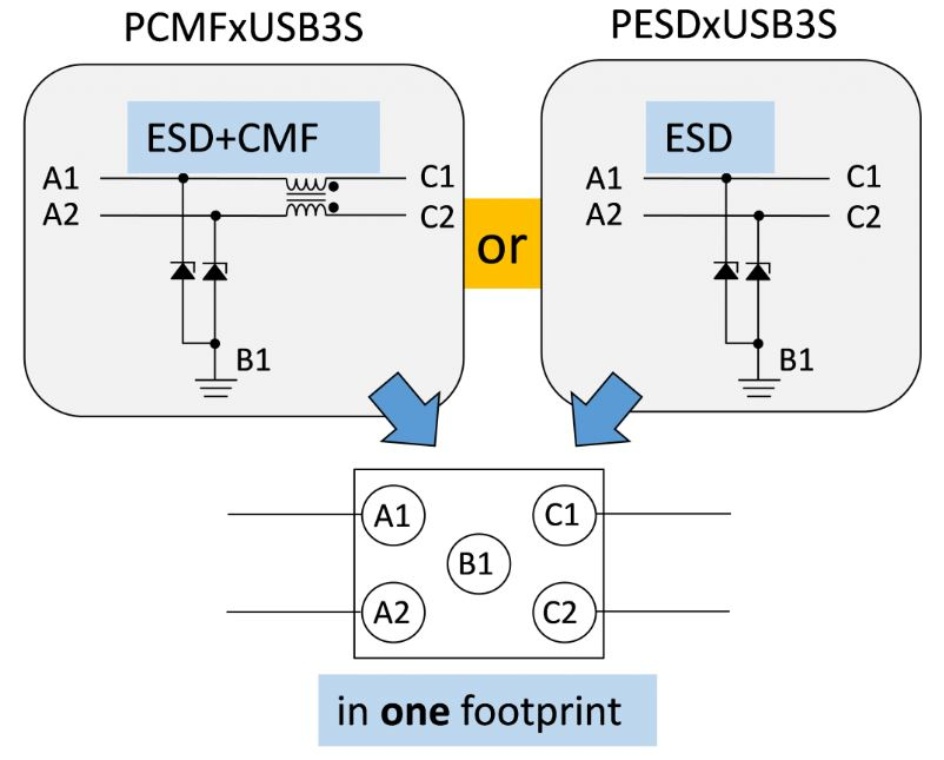
Figure 1. Nexperia offers CMFs with ESD protection (left, PCMF-series) and ESD protection (right, PESD-series) in the same footprint to allow short-term changes between PCMF and PESD without board redesign.
However, there are less obvious reasons to combine a CMF with ESD protection in one single device. Taking a look at separate ESD protection devices and separate CMFs (without sufficient, low-clamping ESD protection), both stages alone still can offer sufficient signal integrity for the differential signal, while the combination of standalone CMF and ESD-protection doesn’t offer this signal integrity any more.
A way of measuring the limit of the bandwidth is the frequency, where the differential signal is attenuated by 3 dB, compared to the signal at low frequencies. An attenuation of -10 dB on a log10 scale means one order of magnitude (or 1/10 th) of the signal strength in terms of power, an attenuation of -20 dB 1/100 th, and so on.
The ratio between the ingoing and outgoing signal is displayed over the Scattering- or short S-Parameter, where S21 shows the signal travelling between ports 2 and 1, S21dd means differential in, differential out.
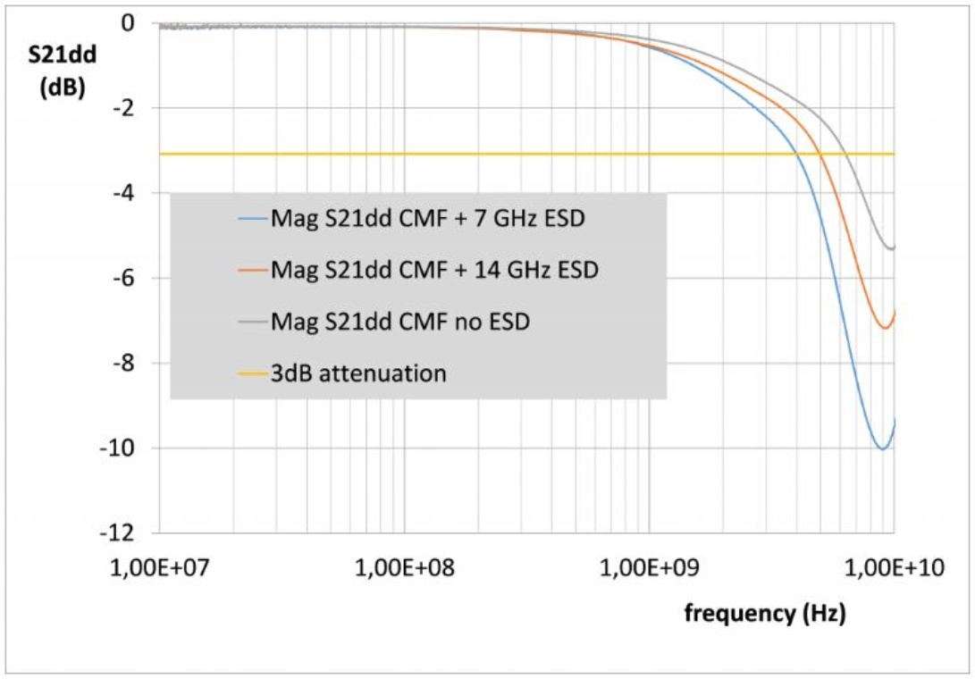
Figure 2. S21dd is the ratio of the ingoing to the outgoing differential signal, in dependency of the frequency. The frequency, where the signal is attenuated by 3 dB, is the limit of the differential pass-band. The curves show the attenuation for a Ferrite-based CMF without ESD protection, and the same filter, when adding ESD protection having a pass-band of 14 GHz or 7 GHz. The 3dB frequency decreases from 6.3 GHz to 4.9 GHz or 4 GHz. When comparing the RF behaviour of CMFs, it is necessary to compare the complete performance.
Looking at an example where the ESD protection has a differential pass-band of 14 GHz and the CMF has a differential pass-band of 6.3 GHz, we found, that the combination of both gave a pass-band of only 4.9 GHz. So, it is important to compare the performance of the complete solution, including ESD protection. In contrast, when looking at an integrated CMF with ESD protection, the PCMFxUSB3S, the combination of both functions, CMF and ESD protection, still offers a typical pass-band of 6.5 GHz.
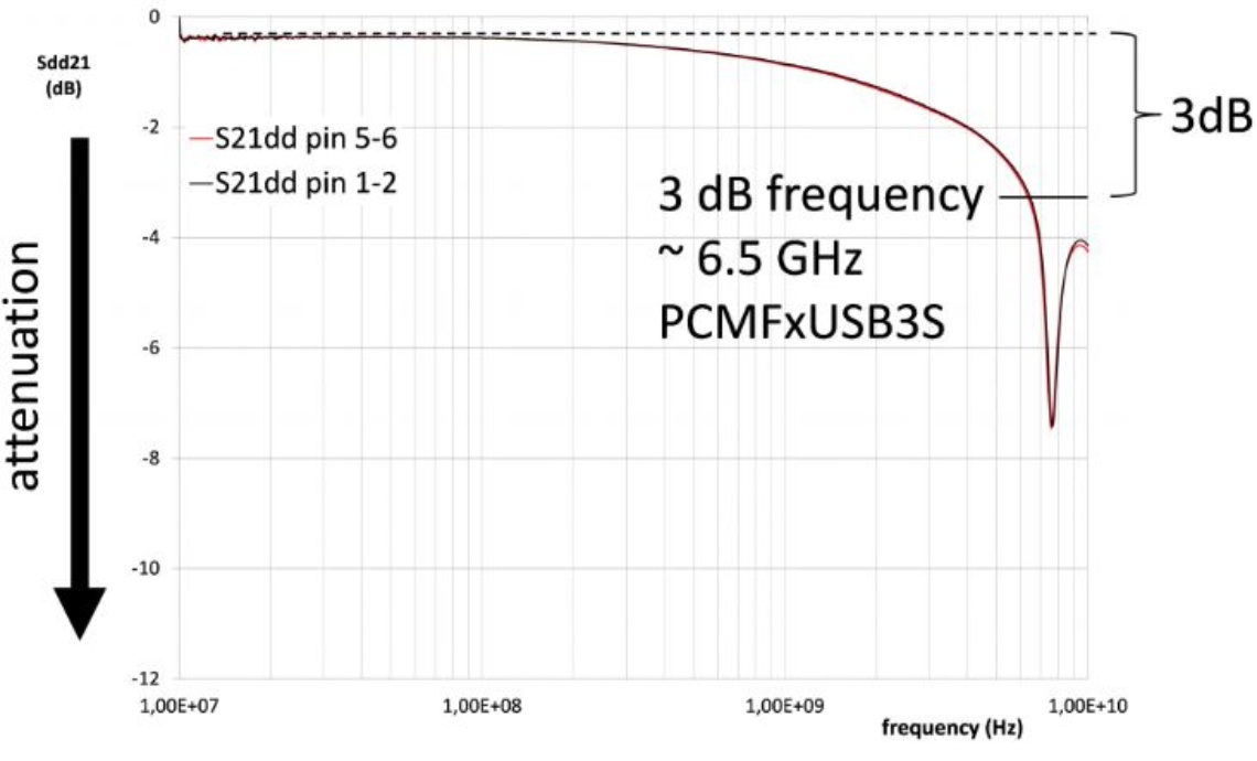
Figure 3. Differential pass-bands of an integrated CMF with ESD-Protection, PCMF3USB3S compared for the line pairs at pins 1-2 and 5-6. A high symmetry between line-pairs helps to avoid data skew.
PCMFxUSB3S offers an unsurpassed differential pass-band, when the required ESD protection is taken into account. On top of it, a high symmetry avoids run-time differences between single lines and line-pairs, which can cause data skew. Data skew can close eye diagrams on the time scale.
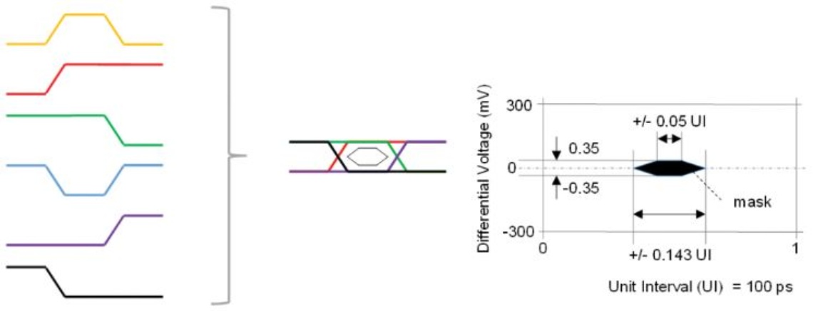
Figure 4. Eye diagrams are overlays of all possible 1-0 and 0-1 signal transitions (left side). The mask (right side) must not be violated by any of these transitions to offer receivers the minimum acceptable signal integrity.
A practical example can be seen in Fig. 4, which compares the eye-diagram of a PCMF2USB3S at 10 Gbps (highest USB3.1 speed level) to the reference board without Device Under Test (DUT)
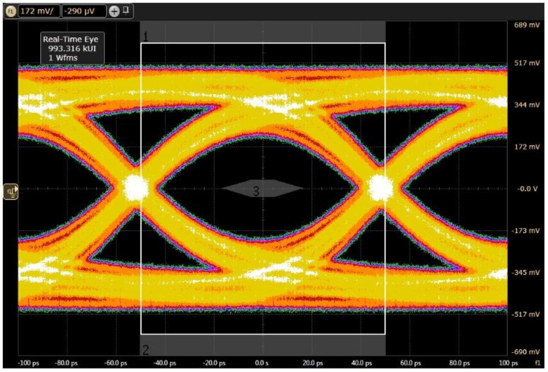
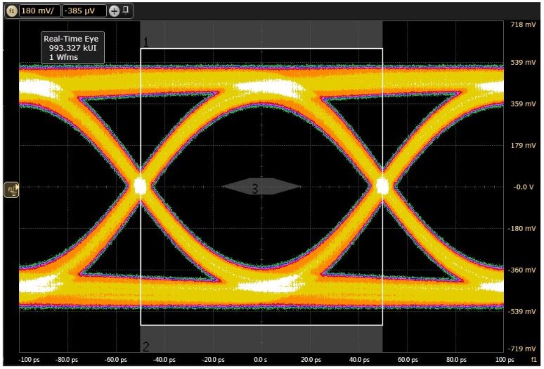
Figure 5. Comparing the USB3.1 eye diagram at 10 Gbit/s for PCMF2USB3S on a test board.
PCMF2USB3S passed the USB3.1 compliance test at 10 Gbit/s on our test board in an external lab. Since data rates at these speed levels obviously needs careful RF design, Nexperia is able to share with you an example layout around the new USB Type-C connector.
The HDMI standard uses eight high-speed differential TMDS lines for audio/video data. With the transition to HDMI2.0, there came the challenge for many design engineers that consumers keep the cables they purchased for HDMI1.4 data rates. So, instead of demanding higher quality cables, HDMI receivers are expected to handle signals, which are distorted by a worst cable model and additional data skew, at test-point 2 (TP2).
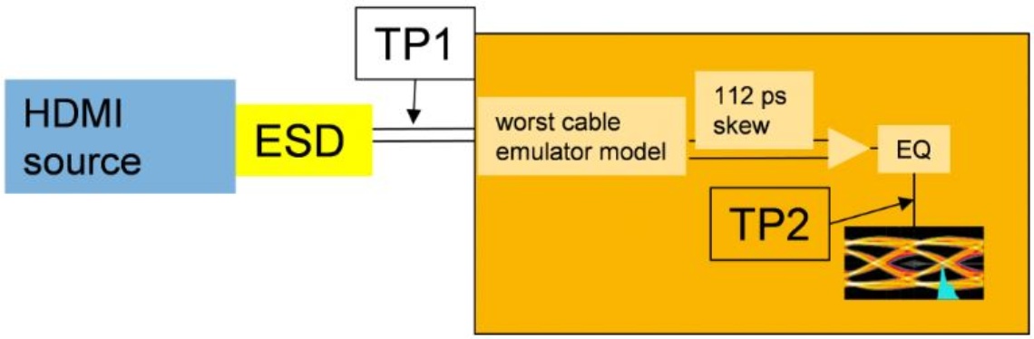
Figure 6. while the traditional eye-diagram for HDMI is measured at test-point 1 (TP1), a second measurement with “worst cable emulator” and additional skew is added at test-point 2 (TP2) to reflect the usage of HDMI1.4 cables for HDMI2.0 data rates
The remaining eye at TP2 still must not violate the mask:
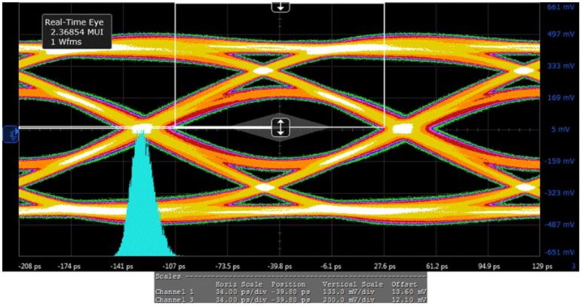
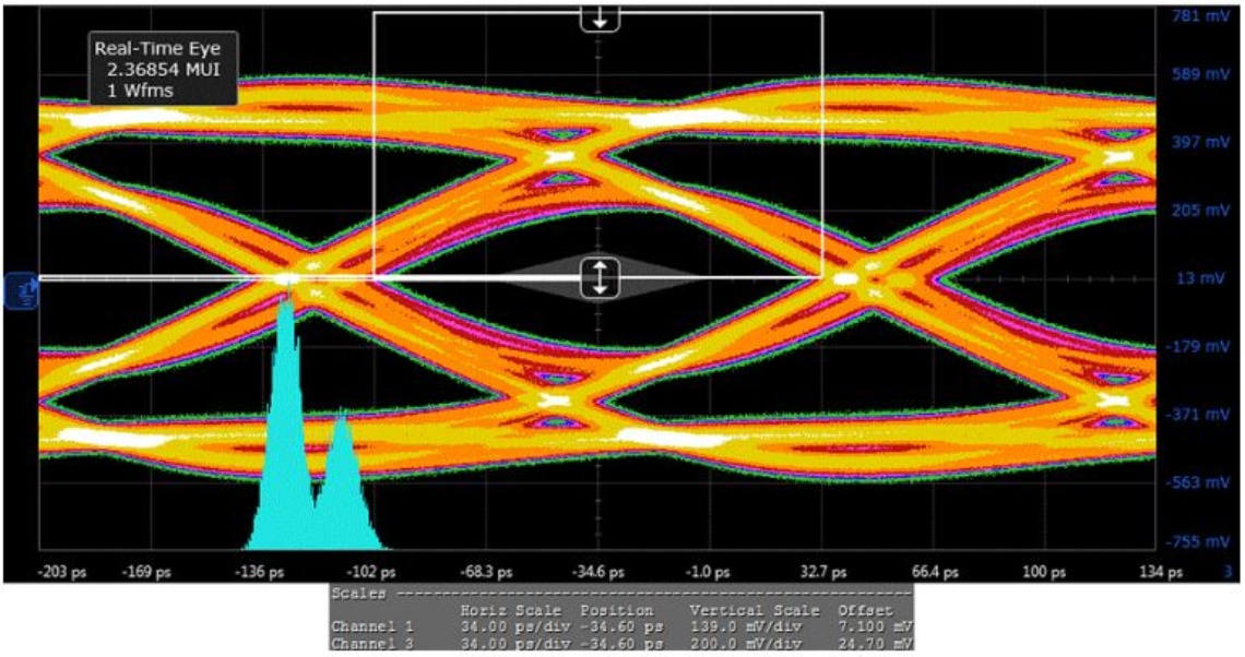
Figure 7. Eye diagram of PCMF2HDMI2S on a test board with “worst cable emulator” (upper diagram) and additional skew at test-point 2 (TP2) and reference eye without Device Under Test (DUT) on a test board (lower diagram). Although the eye-diagrams look a bit unfamiliar, this is a very good “pass” result. The familiar eye diagrams at TP1 look very much nicer, obviously, and can be found in the data sheet of PCMFxHDMI2S.
Another reason for integrating CMF and ESD protection to one device is that every disturbance of the impedance on the signal line-pair will reflect a part of the signal. If several disturbances are distributed along the signal path, it can lead to multiple reflections interfering with each other, severely compromising the signal integrity and close eye diagrams. Some data standards, for example for the TMDS lines of the HDMI standard, limit the number and the amount of such impedance deviations from the data line impedance.
The variation of the impedance over the signal path is shown by Time-Domain Reflectometry (TDR) measurements, where the running time of the signal is proportional to the distance over the signal path. For USB3.1, the differential impedance should be 90 Ohms, for HDMI TMDS 100 Ohms. If an additional part in the signal path is adding more capacitive load, the signal will decrease the local impedance below the target value, if this additional part is adding more inductive load, the local impedance will be above the target value. Any deviation of the impedance, be it capacitive or inductive, will cause such signal reflections.
One example can be seen in Fig. 8, where the variation of the impedance over the running time (distance) is shown for two different integrated CMFs with ESD protection. For reference, the impedance of the test boards without Device under Test (DUT) is shown. While one device, PCMFxHDMI2S, shows the impedance dip that corresponds to a standalone ESD protection device with a very low capacitance, the other integrated CMF shows an inductive behaviour, which violates the limits given by the HDMI standard.
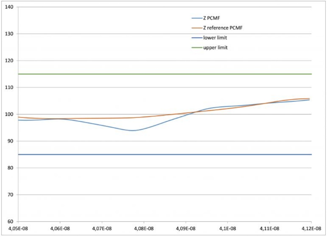
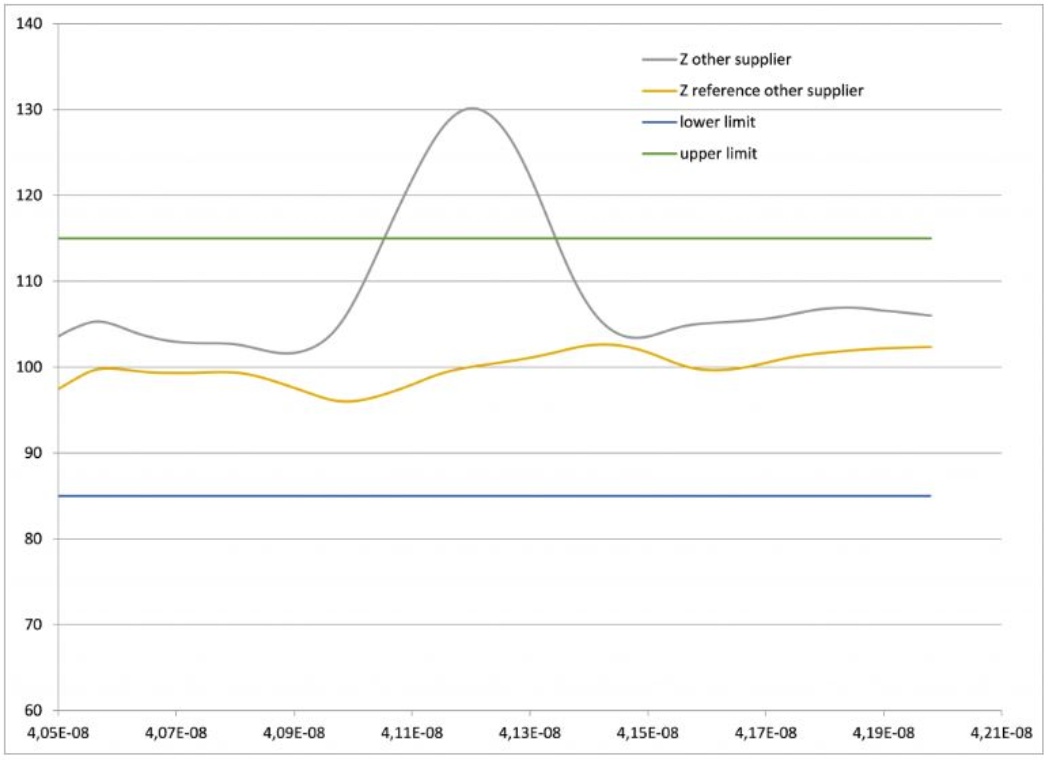
Figure 8. TDR (Time-Domain Reflectance) measurement of two integrated Common Mode Filters with ESD protection using a 200 ps filter (according to the HDMI standard). The impedance Z is measured over the running time (distance). The PCMF filter stays clearly inside the limits set by the HDMI standard, while the compared filter is too inductive to pass this test. Both filters are compared to the reference boards without filter (undisturbed transmission line). The time scales are different due to different board positions and device dimensions.
Since the new Type-C connector makes it possible to send, for example, HDMI data as well over the USB3.1 interface, it becomes more important to fulfill several standards with devices used for this interface. But even, if HDMI compliance is not needed, minimizing the influence of the impedance introduced by a device will minimize reflections and support good signal integrity for all data standards.
Summing up the first part: It is important to select a solution with a wide differential pass-band to make sure, that the signal goes through and to compare complete solutions with CMF and ESD protection combined, when it comes to the signal integrity.
Since a CMF is chosen to suppress unwanted noise, the common mode rejection is obviously an important parameter as well. The common mode rejection is again plotted as an S-Parameter over the frequency, in this case S21cc. Again, an attenuation of -10 dB will mean one order of magnitude (1/10) less power of common mode noise.
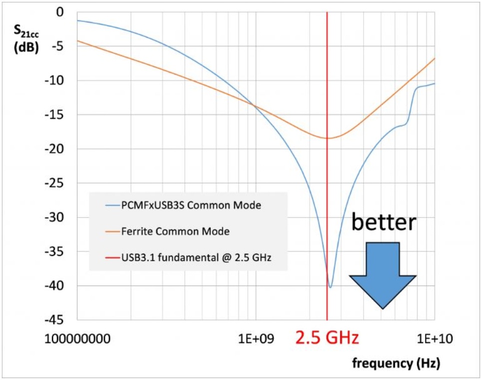
Figure 9. Comparing the common mode rejection of PCMFxUSB3S to the USB3.1 ferrite filter shown in Fig. 1. Since interference between the USB3.1 5 Gbps fundamental at 2.5 GHz with WiFi, Bluetooth and LTE-bands at 2.5 GHz needs to be avoided, a strong rejection in this frequency range is exceptionally important. The rejection of PCMFxUSB3S clearly exceeds -30 dB (less than 1/1000 in terms of common mode power) around 2.5 GHz and offers a rejection of more than one order of magnitude in terms of power between 700 MHz and 10 GHz, covering all GSM/3G/LTE/WiFi/GPS/Bluetooth frequencies with a broad-band common mode rejection.
When selecting a common mode filter, focus on having a strong common mode rejection for the fundamentals and higher harmonics of the wireless and wired data standards, which need to be isolated from each other. For USB3.1 at 5 Gbps, the fundamental at 2.5 GHz is in the middle of a crowded wireless frequency band (LTE, WiFi, Bluetooth) and needs exceptionally strong rejection in this area. For HDMI2.0, the frequencies between 1,7 and 3 GHz are most critical. At the same time, the common mode rejection should have a bandwidth wide enough to suppress potential noise issues at less prominent frequencies.
So far, we have covered how to establish signal integrity and common mode noise suppression. But, how good is the clamping of ESD pulses to protect sensitive transceivers?
Looking at transceivers for very fast signals, like USB3.1, our experience is that the ESD survival level of the complete system is not defined by the ruggedness of the ESD protection device, but the clamping behaviour. In other words, how much remaining ESD is passed on by the ESD protection device? This is the case for all transceivers, which we have measured so far. Having said this, our PCMF/PESD series nevertheless offers a ruggedness against IEC 61000-4-2 ESD pulses of 15 kV contact, which exceeds the highest level 4 of this IEC-standard. PCMFxUSB3S and PCMFxHDMI2S as well as the PESDxUSB3S are all building on Nexperia’s TrEOS protection technology, which combines industry-leading switching speed (0.5 ns) with lowest dynamic resistances and a high robustness against 8/20 surge and ESD pulses.
How good are these new CMFs when it comes to protecting very sensitive transceivers? We tried the PCMFxUSB3S in combination with the most sensitive USB3.1 transceiver we found yet and confirmed a robustness level of this combination of more than 15 kV IEC 61000-4-2 in several passes. Apart from dealing with common mode issues efficiently, the PCMF is the most efficient solution we found up to now (April 2016), when it comes to handling USB3.1 frequencies while still protecting very sensitive transceivers against ESD.
Some ferrite/ceramics based CMFs offer integrated ESD protection; since they have clamping voltages of several 100 volts, they will offer no additional protection to sensitive transceiver chips. Fig. 9 shows a comparison of a ceramic/ferrite filter with integrated ESD protection to an older PCMF process generation.
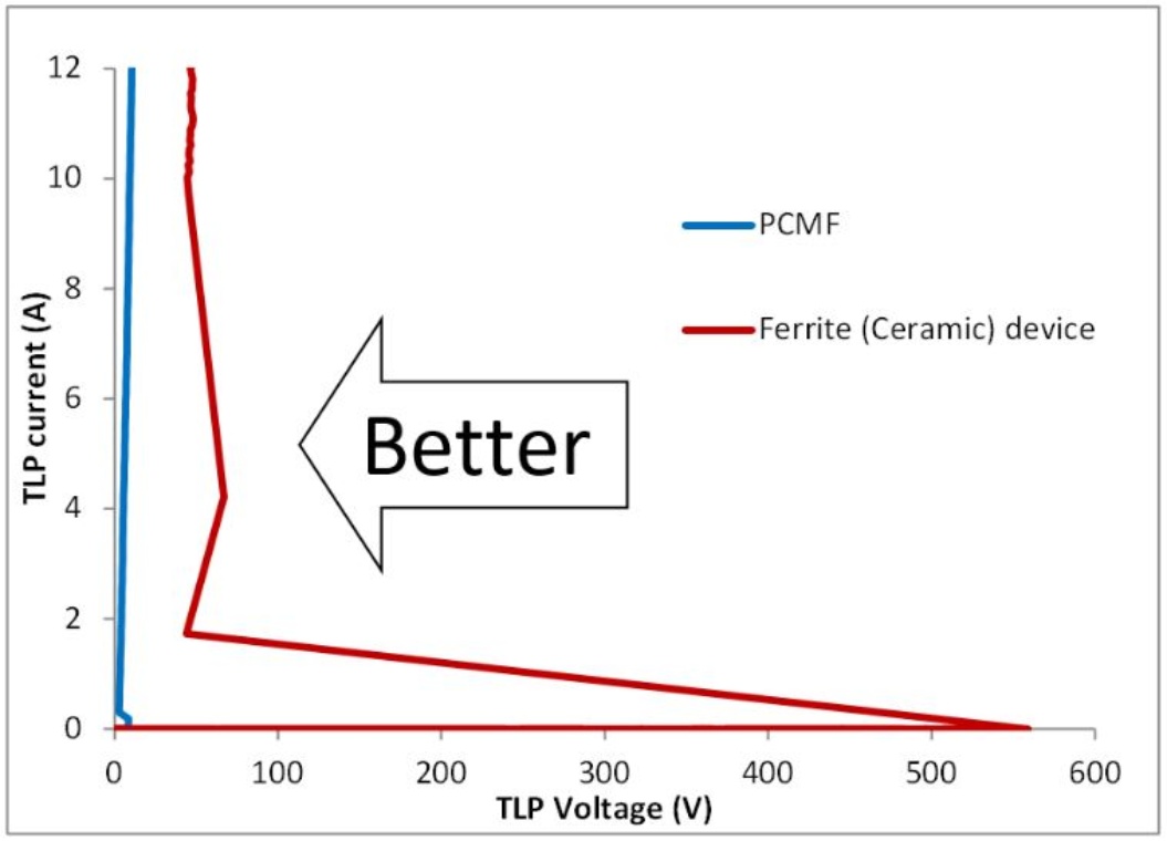
Figure 10. comparing the TLP clamping of an integrated CMF with Silicon-based ESD-protection and a ferrite CMF with integrated ESD-protection. PCMFxUSB3S, PCMFxHDMI2S and PESDxUSB3S offer even lower clamping, however, this would be lost in the scale needed to display the TLP behaviour of ferrite-based ESD protection.
Since ferrites are obviously no competition when it comes to ESD clamping, how does the PCMFxUSB3S series compare to other CMFs with silicon-based ESD protection? Short answer PCMFxUSB3S offers the lowest clamping compared to all other Common Mode Filters.
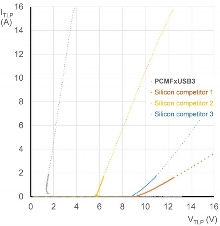
Figure 11. Comparing the TLP clamping of the PCMF series to other CMFs with integrated ESD-protection.
In summary, when looking at protection and filtering for very fast data lines, we have identified these topics:
- The differential signal must be able to pass the protection and filtering solution, as shown by the differential pass-band and eye-diagrams, which are also needed to pass compliance standards.
- Adding additional ESD protection to standalone CMFs will introduce significant degradation to the system, even if both devices alone show a good RF performance.
- The common mode rejection at critical frequencies such as 2.5 and 5 GHz for USB3.1 must be high.
- The ESD clamping must be low.
And finally, it should be possible to swap CMFs with ESD-protection to ESD-protection-only to avoid re-designs and to support a shorter time-to-market.