The ‘thermal characteristics’ sub-section of the datasheet for a semiconductor device includes information about its thermal behaviour in respect of different reference points and operating conditions. Therefore, designers need to understand the meaning of these parameters to ensure their circuits' safe and reliable operation, especially since device manufacturers sometimes specify these parameters differently. This article explains how Nexperia defines the thermal parameters in its datasheets.
Understanding thermal resistance in greater depth
Thermal resistance Rth is the steady-state parameter of how much a device heats for a constant amount of power dissipated under DC conditions, expressed in units of Kelvin per Watt (or degrees Celsius per Watt). However, since thermal resistance describes temperature difference, both units are equivalent. The subscript j-x states the temperature difference from the junction to a reference point—the primary heat flow pathways in the cross-section of the typical clip-bond packaged device in Figure 1.

Nexperia describes the thermal characteristics of its devices using two different thermal resistance parameters. The first is from the device junction to the ambient environment (j-a), and the second is from the junction to the solder point (j-sp) of the cathode (Figure 1).
The minor thermal heat pathway from the junction to the topside of the case (is also shown as it is relevant when considering topside cooling packages (like CCPAK12). On the other hand, the primary heat pathway for surface mount devices (SMD) is from the junction to the solder point on the PCB. Therefore, when using Rth(j-a) to compare packages from different vendors, it is essential to check parameters like PCB type and footprint, which also significantly impact Rth(j-a). For illustrative purposes, the thermal characteristics (under DC conditions) for Nexperia’s PMEG45T20EXD-Q 45 V, 2 A Trench Schottky barrier rectifier are shown in Table 1.
Nexperia specifies values for Rth(j-a) in two different mounting conditions. The first is for a standard footprint, where thermal resistance is highest (as there is a limited pathway for heat dissipation), and the second is with a 1 cm² heat sink at the cathode.
Rth(j-sp) characterises the heat transfer from the junction through the lead frame to the solder point of the cathode tab. Therefore, it is not affected by the type of PCB or footprint chosen, so it is unnecessary to state the mounting position.

Preventing thermal runaway
Figure 2 shows two thermal images (captured using an infrared camera) for the PMEG45T20EXD diode operating with continuous power dissipation of 1.07 W—one for a standard footprint and one using a 1 cm² heat sink—the benefit of a heat sink is clear to see. The temperature difference in thermal equilibrium exceeds 30 °C. Note that the infrared camera only captures the topside temperature, and that the actual junction temperature is higher than the value shown.
 and with a heat sink (bottom)")
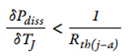
A diode can fail when the reverse power losses generated within the diode (due to leakage current) exceed the amount of heat that the package can dissipate and is called ‘thermal runaway’. To prevent this from happening, the amount of power dissipation should adhere to the following formula:
Dynamic thermal behaviour
Since thermal resistance, Rth describes the steady-state behaviour, thermal impedance—denoted as Zth—is used to represent the dynamic thermal behaviour of a device. Since Zth(j-x) is a dynamic parameter, it is represented graphically as a function of pulse duration for different duty cycles, as shown in Figure 3 for the PMEG45T20EXD-Q. A duty cycle of 0 denotes single pulse operation, while a duty cycle of 1 indicates DC operation.
 as a function of pulse duration and duty cycle for the PMEG45T20EXD-Q")
The graph shows that devices can sustain more power dissipation for small duty cycles or short-duration pulses, with the following equation describing the increase in junction temperature for a specified amount of power dissipation where Pdiss is the power dissipated by the diode:
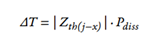
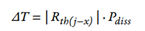
Zth(j-x) indicates how a device responds to transient thermal events and converges to the thermal resistance Rth for a long pulse duration. In steady-state conditions, the above equation becomes:
Summary
Thermal resistance is a parameter commonly specified by semiconductor manufacturers in their device datasheet’s ‘thermal characteristics’ section. This article shows how Nexperia provides designers with additional detail about this parameter, enabling them to derive optimal thermal performance from their circuits. For more information, please see Nexperia’s Diode Application Handbook.
To find space saving, thermal optimized and robust package solutions for the diodes and transistors in your next design, head over to our dedicated landing page: nexperia.com/save-pcb-space