The expectations of travel and human interaction with vehicles is changing dramatically. As such, mega trends of increased connectivity, autonomous driving and electrification are pushing the evolution of automotive wiring harnesses and driving the growing demand for high-speed data transmission and bandwidth to realize advanced driver assistant systems. All of which needs to be protected from ESD spikes and surges.
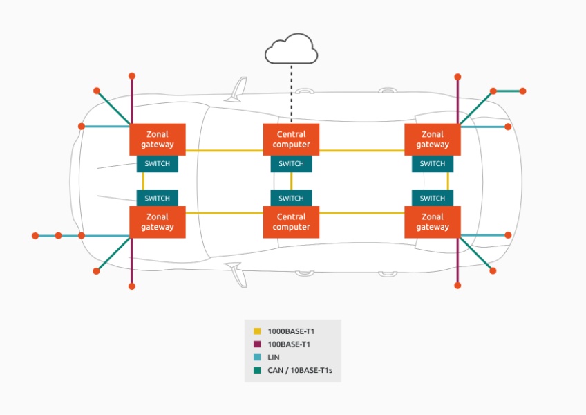
Traditional wiring looms and in-vehicle networks have been undergoing a significant transformation. The classic flat architecture wiring harness is changing to a domain and zonal architecture with Automotive Ethernet as the backbone (see SEED delivers OPEN Alliance compliant ESD protection). However, peripheral buses still need to transmit more data so new versions of existing protocols are finding their way into vehicle networks. The CAN bus is synonymous with in-vehicle networks but was limited to 1 Mbit/s until the launch of CAN-FD (Flexible Data), which covers speeds up to 12 Mbit/s and offers critical advantages necessary for future ADAS applications.


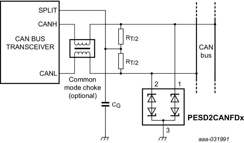
2 Mbit/s is the typical implementation limit suitable for many applications that do not require higher data rates. CAN-FD uses the same differential signal levels as high-speed CAN. The increased data rate is achieved by shortening the dominant and recessive states of a send message. This technique increases the requirements on the physical layer and as systems become more sensitive with regards EMC and ESD, it requires additional, discrete ESD protection to improve system ESD robustness to a reliable level.
Besides car OEM requirements, ESD protection devices must fulfil industry standards such as IEC61000-4-2 or ISO10605 for automotive. For CAN (FD) bus, ESD devices must be short-to-battery and jumpstart robust according to ISO16750-2 (26 V) or internal norms (28 V). Compliance with IEC62228-3 in combination with a CAN transceiver (Emission, Immunity: DPI, Pulses, ESD) is also necessary. In addition, common requirements for CAN are diode capacitance of 17 pF to 30pF max and for CAN-FD 6 pF to 10 pF, as the data speed is greater and signal integrity is more is critical as well as capacitance matching. Thus, Nexperia improved its IVN product series and developed a new generation tailored to CAN-FD requirements. The new PESD2CANFDx series comes in different voltage, capacitance and packages configurations while being 2x AEC-Q101 qualified.

The advantages of going leadless
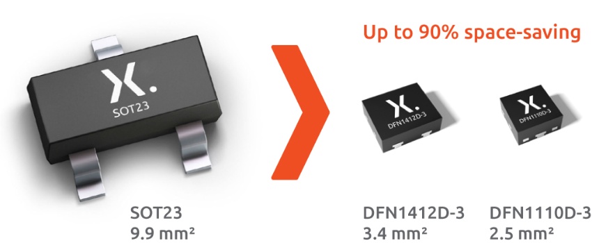
Advantages of leadless CAN-FD in DFN packages over classical SOT packages are not only significant PCB space saving but especially the improved signal integrity which is critical for SSD protection. For signal integrity, the routing is a crucial point. Even though, the parasitic capacitance deteriorates the signal quality, at very low capacitances, the routing that is done to connect the package plays an important role. The most important general finding complies with best practice signal integrity design: avoid switching layers, avoid using stubs.
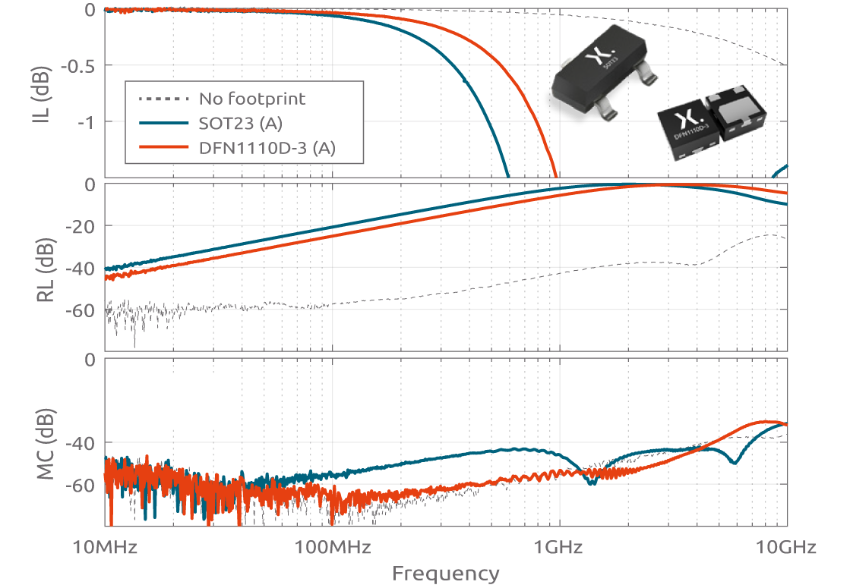
S-parameters are a common way to measure the signal integrity. The parameters shown are differential insertion loss (S21dd), return loss (S11dd), and differential to common mode conversion (S21dc). The following measurements are conducted with a VNA and the system was calibrated to the probe tip, so the traces before and after the footprint are not de-embedded. Figure 3 shows the same routing schemes with a PESD2CANFD24V-T in SOT23, PESD2CANFD24V-QB in DFN1110D-3, both with max. diode capacitance of 6 pF, and dashed lines refers to the case of straight traces without any footprint. It is seen that the very similar performance of the empty footprints starts to deviate when devices are mounted. Here, the leads of the SOT23 package appear as stubs and the larger structure inside the package adds greater parasitics. As such, the DFN solution shows better signal integrity especially for insertion loss (IL) and common mode conversion (MC) compared to the leaded alternative.

For more specific product information and datasheets please take a look at the latest selection table.