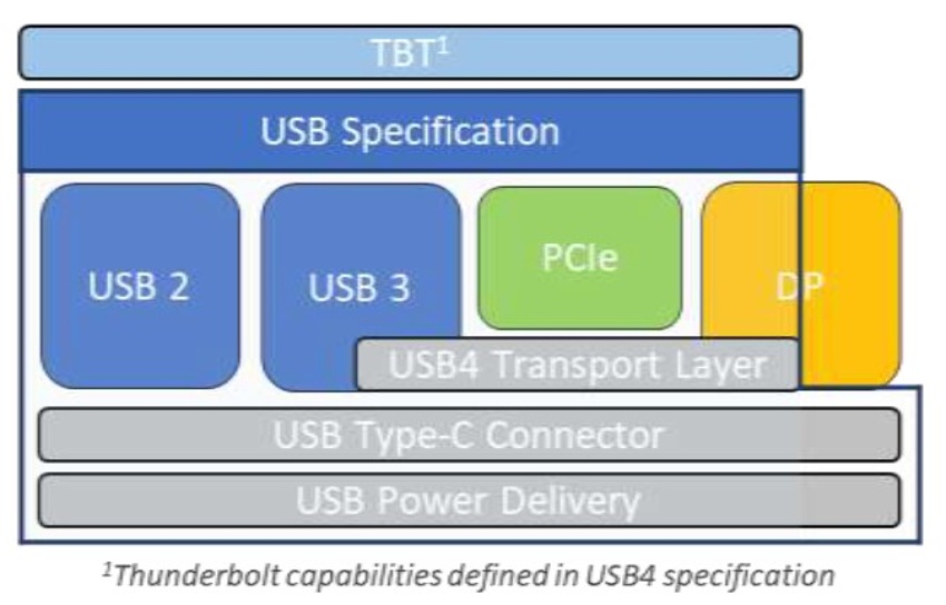
At the beginning of September last year, the USB Implementers Forum (USB-IF) announced the publication of the USB4 specification. Offering backward compatibility with USB 3.2, USB 2.0 and Thunderbolt 3, the new specification utilizes the USB Type-C® connector but doubles the bandwidth to extend Type-C performance. That calls for the improved ESD protection offered by Nexperia.

With the USB4 specification comes a new underlying protocol that allows connections to scale to the best mutual capability of connected devices. For example, it can scale allocations for display data flow given USB Type-C has evolved into the external display port for many host products. It can also help optimize performance for older devices. However, this means the new protocol includes some changes that have consequences for the selection of ESD protection components.
Key characteristics of USB4 include:
- Two-lane operation using USB Type-C cables and up to 40 Gbps data transmission over certified cables
- Multiple data and display protocols that efficiently share the maximum aggregate bandwidth
- Backward compatibility with USB 3.2, USB 2.0 and Thunderbolt 3
- Supports USB Power Delivery specification
The TrEOS pillars of ESD protection
Obviously, ESD protection needs to add low insertion loss (signal attenuation) and low return loss (signal reflection) to the system, while offering low clamping to protect sensitive high-speed data lines. So, in many ways Nexperia’s TrEOS ESD protection technology with active silicon-controlled rectification is the ideal solution. And with the PESD2V8R1BSF, designers’ have access to a winning combination of extremely low capacitance (0.1 pF), extremely low clamping (dynamic resistance 0.45 Ω) and very high robustness against surge and ESD pulses (4.5 A 8/20 µs for very fast datalines).
But as with any ESD protection, at Nexperia we understand that to choose the right device engineers need to look at performance and placement from a system level approach. That is why we use our System-Efficient ESD Design (SEED) approach (as outlined in Chapter 5 of the ESD Application Handbook – Protection concepts, testing and simulation for modern interfaces). And when comparing USB4 and USB 3.2 specifications, we uncovered a potential issue that may be easily overlooked – operation voltage.
Backward compatibility and operation voltage
Apart from being able to ignore the plug orientation, the main benefit of USB Type-C for the end customer is the ability to connect two different applications and leave it up to them to negotiate the optimal connection. In our whitepaper ‘Choosing ESD protection devices for USB4™’, we looked at potential ESD protection and placement issues arising from having different operation voltages but using the same USB Type-C connection.

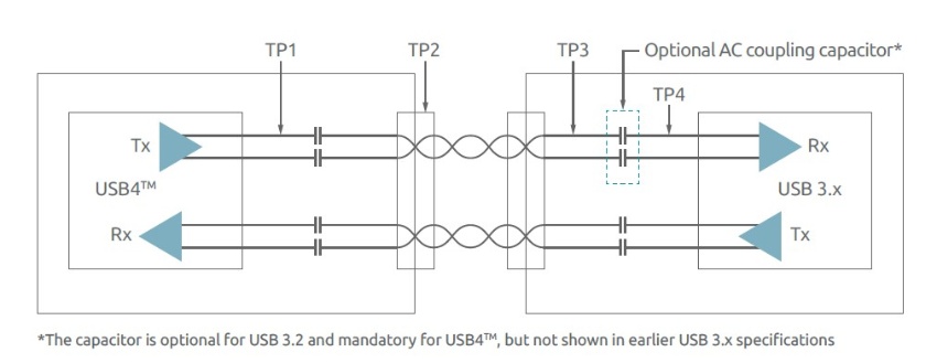
One thing to note is that for USB4 it is mandatory to have AC-coupling for the receiver inputs (Rx). That means ESD protection can either be placed directly at the inputs of the SoC behind the coupling capacitors or at the port side before the coupling capacitors. In the first case low VRWM devices can be chosen with ultra-low clamping voltages, achieving best protection for very sensitive inputs. By placing protection before the coupling capacitors means they are also protected, but VRWM is normally chosen as high as the maximum expected VBUS on the Type-C connector. For both application scenarios Nexperia can offer suitable solutions.
For more technical on modeling and simulation of ESD system protection, you can also take a look at the 2018 ECMS paper – Predicting system level ESD performance.