A brief introduction into why the capabilities of power MOSFETs make them ideal for automotive applications like 48-volt starter generators
After talking about the 48-volt architecture (“The appearance of 48-volt mild hybrid”) and describing some of the main applications (“The 48-volt starter generator”), it is imperative we delve into the electronic requirements of these new systems. In this blog, I briefly introduce power MOSFETs and discuss their role in automotive applications such as the 48-volt starter generator.
The rise of automotive semiconductors
Semiconductors are an essential element in today’s technical applications because of their ability to both conduct and insulate the flow of electricity under certain conditions. In a way they act as the ‘valves’ of the system, controlling the flow of electricity in the electronic circuit. And of course, systems require different types of devices depending on what the desired outcome is – rectification, amplification or switching for example.
Power semiconductors are used in many automotive applications, including the 48-volt starter generator. The main benefit of these devices is their ability to withstand high voltages and large currents without being damaged. In the last decade, power requirements of automotive applications significantly increased which led to the higher demand for efficient power semiconductors.
So what is a power MOSFET?
There are different types of power semiconductors - power diode, thyristor, bipolar-junction transistor (BJT), insulated-gate bipolar transistor (IGBT) and the metal-oxide-semiconductor field-effect transistor (MOSFET). The use of each one of these devices depends on the application’s requirements.
Putting our focus on MOSFET devices, these are voltage-controlled switches with faster switching capability compared to other power semiconductors. This is particularly useful for applications which require fast operational speeds (e.g. motor control). Figure 1 shows the schematic representation of a basic MOSFET device.

Figure 1: Schematic diagram of a MOSFET
The MOSFET is controlled through a Gate terminal which acts like a bridge between the Drain and Source terminals where the current flows. This bridge can be opened and closed depending on whether a voltage is applied to the terminal. How much current flows between the Drain and Source is proportional to the amount of voltage applied.
Depending on how the transistor is fabricated and which material is used to create the channel affects how the gate works. In N-channel semiconductors, most of the charge carriers are electrons, while in P-channel types the charge carriers are electron holes. In other words, N-channel devices require a positive gate voltage while P-channel need negative gate voltage to operate.
Role of power MOSFETs in 48-volt starter generator
Having scratched the surface of MOSFETs, it is worth discussing how such devices find their place in the 48-volt starter generator. The starter generator consists of a multi-phase motor which needs to be managed by a sophisticated control circuitry. MOSFETs provide the muscle in 48V systems, and prove to be advantageous over older BJT switches because of their lower conduction losses and faster switching speed. Figure 2 displays a typical 3-phase motor control circuit which utilizes 6 MOSFET switches in an H-bridge configuration. The reason for phasing is to provide better efficiency of operation as well as cost.
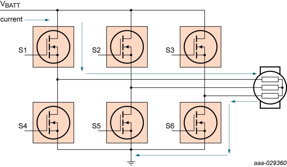
Figure 2: 3-phase brushless DC motor control using N-channel MOSFETs (Figure from Andy Berry, Nexperia automotive application engineer)
In a motor control circuit, only one switch from the power supply side and one from the ground end can operate at a single time, provided they are not connected in series. For example, closing S1 and S6 gives a smooth connection whereas closing S1 and S4 together will lead to a short circuit. Furthermore, the transition between switch phases needs to be managed carefully to avoid mis-connections. This is achieved by a short dead time (normally nanoseconds) where all switches are open.
Figure 2 also highlights the correct flow of current for one of the phases where the flow goes through S1, then to the motor and finally to ground through S6. The current then transfers to subsequent phases through S2 and S4, and S3 and S5, before going back to the first phase.
Normally, the motor control topology of a 48-volt starter generator can be greater than 3-phase (e.g. 6-phase) to address the needs of higher power and better efficiency. The current flowing to the multiphase motor is typically in the range of 200 A to 520 A. This current is quite significant and imposes the use of MOSFETs with very low RDS(on) and high ID current capabilities.
The switches used in Figure 2 are chosen to be N-channel because of n-type’s lower RDS(on). This leads to less power consumption and lower power losses, where the power losses equal the resistance times the square of the current (Ploss=I2*R). Preferred MOSFET devices must be able to handle ID MAX of 250 A – 300 A per piece and have RDS(on) lower or equal to 1 mΩ.
On the other hand, the MOSFET devices must also be capable of handling the voltage spikes of the 48-volt system. Voltage spikes are short and fast electrical bursts of energy (transients) in the supply voltage. Without such capability, the switch will be easily destroyed. Hence, electronic engineers look at devices able to withstand at least 1.5x times the system voltage. In the case of 48-volt systems, this means MOSFETs with voltage between the drain and source (VDS) [3] of 80 V and sometimes 100 V.
Encapsulated or bare-die
The thermal aspects of MOSFET switches are of great importance in high-power applications. Therefore there is a specific need for reliable MOSFET packaging, capable of meeting exacting thermal requirements and board level reliability. For a 48-volt starter generator, where power levels can reach up to 25 kW, no such packaging solution is available, which forces manufacturers to use bare die (packageless) solutions.
Even though the starter generator is not addressable by a discrete packaged solution, many other 48-volt applications (48/12 V DC/DC converter, electric supercharger, battery management systems, etc.) can benefit from this luxury. Nexperia’s packaged discrete MOSFETs come in different shapes and sizes and are an essential part of vehicle electrification. In my next post I will discuss these packaged solutions in detail and explain how they fit into applications such as the 48/12 V DC/DC converter.